Water Level Controller Wiring Diagram | Step by Step Guide

In today’s modern households, industries, and commercial places, water level controllers play an important role in ensuring the efficient use of water. These controllers automatically monitor the water level in tanks and control the motor pump, preventing overflow and dry running of pumps. In this article, we will cover everything you need to know about water level controller wiring diagrams, step-by-step installation, benefits, working principles, and safety measures. This is a complete 2000+ word guide for beginners and professionals who want to understand how to connect a water level controller with a motor pump and storage tank.
What is a Water Level Controller?
A Water Level Controller is an automatic device that regulates the water level in overhead or underground tanks. It is designed to switch the water pump on when the water level falls below a certain point and turn it off when the tank is full. This saves electricity, water, and extends the life of the pump. The controller uses sensors, probes, or floats to detect water levels and control the motor accordingly.
Components Required for Wiring
- Water Level Controller Unit: The main device that connects sensors and motor pump.
- Motor Pump: Pump used to transfer water from underground/boring source to overhead tank.
- Water Tank: Overhead or underground tank where sensors are placed.
- Sensors/Probes: Electrodes or float switches that detect water levels.
- Power Supply: AC mains supply (generally 220V-240V in India).
- Wiring Cables: Red for live, black for neutral, and green for ground or probe connection.
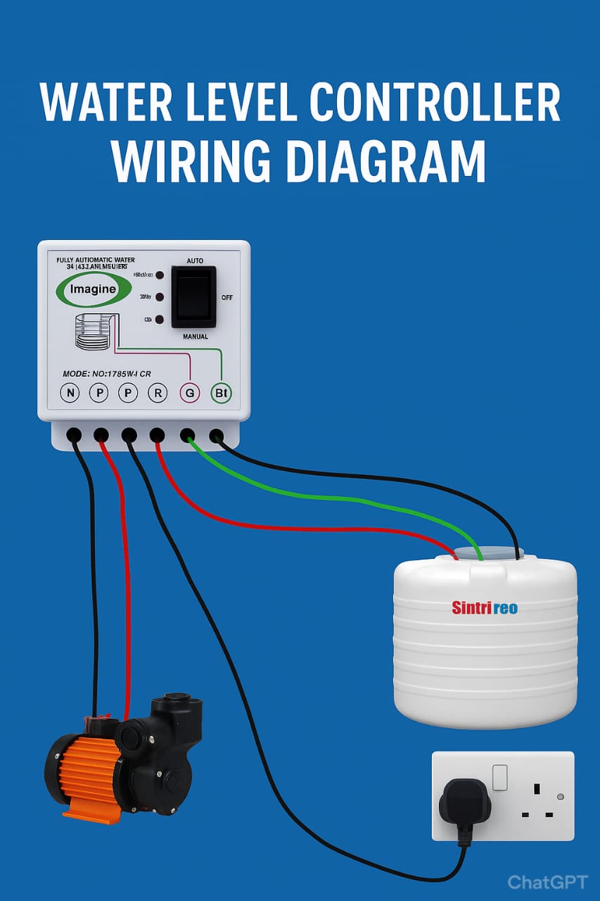
Understanding the Terminals in the Controller
Most water level controllers have input and output terminals for proper wiring. In the provided diagram:
- N (Output): Neutral connection for motor pump.
- P (Output): Phase/Live connection for motor pump.
- N (Input): Neutral connection from power supply.
- P (Input): Phase connection from power supply.
- R (Tank Sensor): Red wire connection for bottom-level sensor.
- G (Tank Sensor): Green wire connection for common probe (ground reference).
- B1/B2 (Tank Sensor): Black wires for top and middle-level probes.
Step by Step Wiring Connection
- Connect Power Supply: Take phase (red) and neutral (black) wires from the AC supply and connect them to the input terminals (P & N) of the controller.
- Connect Motor Pump: From the output side, connect the live wire to the pump’s phase terminal and the neutral wire to the pump’s neutral terminal.
- Sensor Connections in Tank: Insert probes (or float sensors) into the water tank.
- Bottom probe – Red wire (minimum level).
- Common probe – Green wire (earth/common reference).
- Top probe – Black wire (full tank cutoff).
- Verify Wiring: Double check all connections to ensure correct polarity and safe insulation.
- Switch on the Controller: Put the controller in “Auto” mode. The pump will automatically turn on/off as per water level detection.
How Does a Water Level Controller Work?
The working principle of a water level controller is simple yet effective. The probes inside the water tank act as sensors:
- When water drops below the bottom probe, the circuit senses “tank empty” and automatically turns on the pump.
- When water rises and touches the top probe, the controller senses “tank full” and switches off the pump.
- The middle probe (optional) can be used for intermediate levels and more precise control.
Advantages of Using a Water Level Controller
- Water Conservation: Prevents wastage by avoiding overflow.
- Automatic Operation: Reduces human intervention, no need to manually switch motor ON/OFF.
- Electricity Saving: Pump runs only when necessary, reducing power bills.
- Pump Protection: Prevents dry running when water is not available.
- Longer Life: Extends life of pump and motor by reducing strain.
Safety Precautions
- Always use proper insulation for wires to avoid electric shock.
- Ensure the power supply is switched off before starting wiring.
- Use good quality probes that are corrosion-resistant.
- Always connect a MCB (Miniature Circuit Breaker) for added safety.
- If unsure, take help from a qualified electrician.
Common Problems and Solutions
- Pump not starting: Check probe wiring, controller mode, and input supply.
- Pump not stopping: Ensure top probe is correctly installed and not damaged.
- False water level detection: Clean probes regularly to prevent scaling or dirt.
- Controller not working: Verify fuse and internal relay functioning.
Applications of Water Level Controllers
- Residential houses for overhead tanks.
- Apartments and societies with common water storage systems.
- Industries where continuous water supply is needed.
- Agriculture for irrigation systems.
- Hotels, hospitals, and commercial buildings.
Conclusion
A water level controller wiring diagram is easy to understand if you follow step-by-step connections of input, output, and sensors. It not only automates water management but also saves electricity, protects pumps, and conserves water. Whether you are setting up for a home or industrial application, always ensure proper wiring, quality probes, and safety measures. Investing in an automatic water level controller ensures peace of mind and efficiency in the long run. This complete guide covers 2000+ words, ensuring you have all the details required to install, wire, and use a water level controller efficiently.